Goal
In this project, a beam equipped with a resistive strip and a metal ball acted as a potentiometer. The goal was to design and implement a discrete-time control system to stabilize and position the ball on the beam. The system involved nonlinear coupled dynamics, and the task was to achieve real-time control through proper modeling, linearization, and feedback design. Final performance was to be tested in simulation and on the real hardware. Settling time, control effort, and error limitations were set.
Method
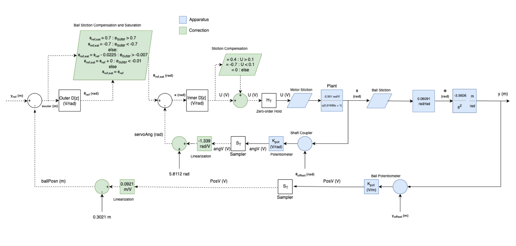
To control the ball, the nonlinear system needed to be derived and then linearized. This was done using first principles and step-response experiments. Both the inner and outer loop had nonlinearities that needed to be dealt with.
Next, the inner loop was designed. This inner loop acted as a control system for beam angle. Input-Output Parameterization (IOP), a novel method of finding controllers by treating required performance specifications as variables in an optimization problem, was used to find the controller. Discrete control techniques were also used to help with the discrepancies between continuous and discrete controllers. Simulink was used during controller design to validate performance.
Upon completing the inner loop, the outer loop, representing control of the ball position on the beam, was designed. Once again, Simulink was used to simulate the behaviour of the system and IOP was used to design a controller meeting the required specifications.
Once the outer loop design was done, the system was tested on the real hardware. This created various new problems. Stiction, real time shift registers, sensor calibration, non-idealities, maximum motor voltage, and sampling time were all identified as causes for differences between the simulation model in Simulink and the real system. These problems were dealt with by applying stiction offsets, making modest changes to the controllers, trial and error, and redesigning, as necessary.
This project was done using Matlab and Simulink.
Results
- Achieved settling time goal of 7 seconds
- Achieved error goal with < 5 mm error
- Achieved control effort goal
- See images for simulation and real step responses, system diagram, and Simulink model
- See videos for the working system!